本文简要描述如何在Lenovo TOR Switch G8052上设置Stacking、LACP、vLAG。本文同样适用于Lenovo
其它型号交换机,包括Lenovo FlexSystem IO Switch模块。
环境准备
2台 x G8052机架式交换机
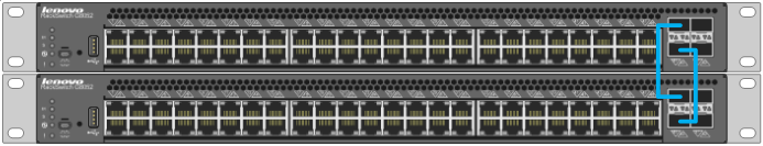
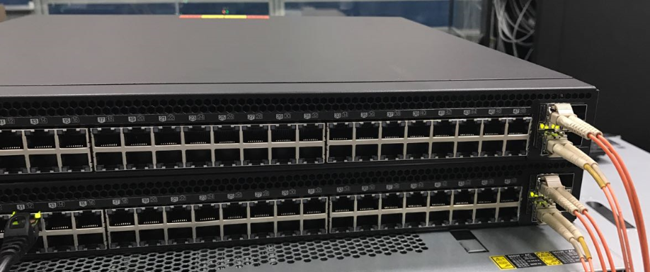
端口链接:
Master XGT1 –Member XGT1
Master XGT2– Member XGT2
什么是Stacking
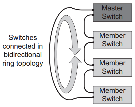
堆叠是指将一台以上的交换机组合起来共同工作,以便在有限的空间内提供尽可能多的端口。多台交换机经
过堆叠形成一个堆叠单元,逻辑上是一台设备,可以由一个管理端口(Mgmt、interface IP或者serial
口)进行交换机配置和管理。堆叠必须在可堆叠的同类型交换机(至少应该是同一厂家的交换机)之间进
行。堆叠将整个堆叠单元作为一台交换机来使用,这不仅增加端口数量,而且增加背板带宽。环境拓扑如
下图:
Stacking配置
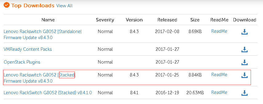
1,确认Switch OS是否支持Stacking,要求是版本8.4或者8.4以上
另外要注意同样的version里面如果有区分Standalone和Stacked,一定要选择Stacked,Standalone是不
支持的。可以在全局模式下使用命令boot stack mode进行验证是否支持stacking
FW/OS升级下载官网:https://support.lenovo.com/us/zh/
2,如果需要升级交换机OS,请参考以下步骤:
准备工作
(a) Firmware交换机微码包括两个文件: boot.imgs 和 OS.imgs
(b) tftp/ftp 服务器,如tftpd32
(c) 确保交换机与 tftp 服务器之间的网终畅通
升级操作
(a) 首先升级 boot 文件
Router(config)#copy tftp boot-image
Address or name of remote host: 172.16.3.28
Source file name: G8052-RS-8.4.3.0_Boot.imgs
Confirm download operation(y/n)? y
(b) Boot 文件升级完成后,升级 image 文件
Router(config)#copy tftp image1
Address or name of remote host: 172.16.3.28
Source file name: G8052-RS-8.4.3.0_OS.imgs
Confirm download operation(y/n)? y
Do you want to change that to the new image2?(y/n) y
Next boot will use new software image1
3,配置Stacking总体流程:
● 在Stacking设备中需要一台Master
● 设置同样的Stacking Link VLAN,默认4090
● 设置专用的Stacking Link,默认万兆口XGE1,XGE2
● 设置管理IP等
4,开始配置
a). 选择一台设置Master,其他设置成Member
参考命令:
Master 交换机:
RS G8052(config)# boot stack mode master
Member交换机:
RS G8052(config)# boot stack mode member
b). 设置stacking Link vlan。默认vlan 4090
参考命令:
RS G8052(config)# boot stack vlan 4090
c). 设置专用的Stacking Link。每个Switch需要2个万兆Stacking链路
RS G8052(config)# boot stack higig¬trunk XGE1,XGE2
d). 重启使上述设置生效
RS G8052(config)# reload
e). 在Master Switch上运行show stack switch 查看Stacking Switch输出显示
参考命令:
RS G8052(config)#show stack switch
Stack name:
Local switch is the master.
Local switch:
csnum - 1
MAC - a4:8c:db:52:92:00
Switch Type - 10 (G8052)
Switch Mode (cfg) - Master
Priority - 225
Stack MAC - a4:8c:db:52:92:1f
Master switch:
csnum - 1
MAC - a4:8c:db:52:92:00
Backup switch: not learnt yet.
Configured Switches:
csnum MAC asnum
C1 a4:8c:db:52:92:00 A1
Attached Switches in Stack:
asnum MAC csnum State
A1 a4:8c:db:52:92:00 C1 IN_STACK
A2 a4:8c:db:52:6f:00 ATTACH
名词解释:
asnum: Attached Switch Number: 由Master交换机根据每个自动分配一个asnum给Member交换机。
asnum主要用作主交换机的内部ID,非用户配置的。
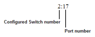
csnum:Configured Switch Number: csnum是堆叠管理员配置的逻辑交换机ID。csnum用于大多数
与堆栈相关的配置命令和切换信息输出。 它也用作端口前缀来区分关系在堆叠中不同交换机的端口之间。
f). 绑定成员到Stacking
参考命令:
RS G8052(config)# stack switch¬number mac
‐or‐
RS G8052(config)# stack switch¬number bind
RS G8052(config)# stack switch-number 2 mac a4:8c:db:52:6f:00
-or-
RS G8052(config)# stack switch-number 2 bind 2
或者最简单的,把Stacking里所有attached设备加入Member
RS G8052(config)# stack bind
Member加完之后显示效果如下
RS G8052(config)# show stack switch
Stack name:
Local switch is the master.
Local switch:
csnum - 1
MAC - a4:8c:db:52:92:00
Switch Type - 10 (G8052)
Switch Mode (cfg) - Master
Priority - 225
Stack MAC - a4:8c:db:52:92:1f
Master switch:
csnum - 1
MAC - a4:8c:db:52:92:00
Backup switch: not learnt yet.
Configured Switches:
csnum MAC asnum
C1 a4:8c:db:52:92:00 A1
C2 a4:8c:db:52:6f:00 A2
Attached Switches in Stack:
asnum MAC csnum State
A1 a4:8c:db:52:92:00 C1 IN_STACK
A2 a4:8c:db:52:6f:00 C2 IN_STACK
g).端口变化
Flex System: INTA1 - 14 is 1 - 14; INTB1 - 14 is 15 - 28; INTC1 - 14 is 29 - 42; EXT ports are 43 - 64; Management ports are 65 – 66
一旦启用堆叠端口编号将更改。使用csnum:端口号标识。例如:
RS G8052(config)# show interface link
Alias Port Speed Duplex Flow Ctrl Link Description
-—— —- —— ——– –TX—–RX– —— ————-
1:1 1 any auto no no down 1:1
1:2 2 any auto no no down 1:2
1:3 3 any auto no no down 1:3
1:4 4 any auto no no down 1:4
1:5 5 any auto no no down 1:5
1:6 6 any auto no no down 1:6
1:7 7 any auto no no down 1:7
1:8 8 any auto no no down 1:8
1:9 9 any auto no no down 1:9
1:10 10 any auto no no down 1:10
1:11 11 any auto no no down 1:11
1:12 12 1000 full no no up 1:12
1:13 13 any auto no no down 1:13
1:14 14 any auto no no down 1:14
….部分输出省略…
1:49 49 10000 full no no up 1:49
1:50 50 10000 full no no up 1:50
1:51 51 10000 full no no down 1:51
1:52 52 10000 full no no down 1:52
2:1 65 any auto no no down 2:1
2:2 66 any auto no no down 2:2
2:3 67 any auto no no down 2:3
2:4 68 any auto no no down 2:4
….部分输出省略…
2:19 83 any auto no no down 2:19
2:20 84 any auto no no down 2:20
2:21 85 any auto no no down 2:21
2:22 86 any auto no no down 2:22
2:23 87 any auto no no down 2:23
… …
5 Stacking配置命令参考
boot stack higig-trunk
boot stack mode {mastermember} [
boot stack pushimage {bootimageimage1image2}
boot stack vlan
copy log [swn
copy log [swn
default boot stack {
logging buffer severity
logging console severity
logging host
[no] logging log stacking
no stack backup
no stack name
no stack switchnumber
show boot stack [
show logging [swn <configured‐switch‐number>] [ { messages reverse severity <0‐7>}]
show stack attachedswitches
show stack backup
show stack dynamic
show stack link
show stack name
show stack pathmap [
show stack pushstatus
show stack switch
show stack switchnumber [
show stack version
stack backup
stack name
stack switchnumber
stack switchnumber
LACP配置
链路聚合(英语:Link Aggregation)是一个计算机网络术语,指将多个物理端口汇聚在一起,形成一个
逻辑端口,以实现出/入流量吞吐量在各成员端口的负荷分担,交换机根据用户配置的端口负荷分担策略决
定网络封包从哪个成员端口发送到对端的交换机。当交换机检测到其中一个成员端口的链路发生故障时,就
停止在此端口上发送封包,并根据负荷分担策略在剩下的链路中重新计算报文的发送端口,故障端口恢复后
再次担任收发端口。链路聚合在增加链路带宽、实现链路传输弹性和工程冗余等方面是一项很重要的技术。
有时候Link Aggregation 也称作port trunking,Cisco有类似的私有协议PAgp(Port Aggregation
Protocol)。的对应的服务器端有NIC绑定(Ethernet/network/NIC bonding)或网卡绑定
(NIC teaming)。
配置步骤:
a). 参与LACP LAG的所有端口必须相同,包括VLAN ID
b). 选择端口并定义admin key。只有具有相同admin key的端口键可以形成LACP LAG
RS G8052(config)# interface port 1:1-1:4
RS G8052(configif)# lacp key 100
c). 设置LACP模式
Passive: 该模式下端口不会主动发送LACPDU报文,在接收到对端发送的LACP报文后,该端口进入协议计
算状态。
Active: 该模式下端口会主动向对端发送LACPDU报文,进行LACP协议的计算。
Off: 关闭,不参与LACPDU报文发送或接收
RS G8052(configif)# lacp mode active
d). (可选,默认)允许成员端口单独参与正常数据流量没有接收到LACPDU
RS G8052(configif)# no lacp suspendindividual
RS G8052(configif)# exit
e). 设置完成后,查看LACP
RS G8052(config-if)# show lacp information
port mode adminkey operkey selected prio aggr trunk status minlinks
1:1 active 100 100 individual 32768 – – down 1
1:2 active 100 100 individual 32768 – – down 1
1:3 active 100 100 individual 32768 – – down 1
1:4 active 100 100 individual 32768 – – down 1
1:5 off 57 57 no 32768 – – – 1
1:6 off 58 58 no 32768 – – – 1
1:7 off 59 59 no 32768 – – – 1
….部分输出省略…
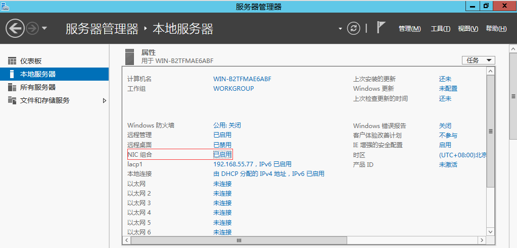
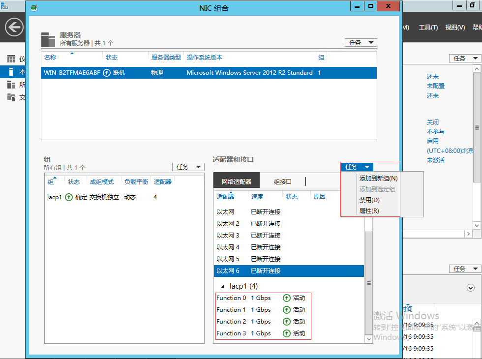
f). 到对应的服务器端进行设置NIC bond。以windows 2012r2为例,添加网卡接口,实验中使用板载的
4个万兆口


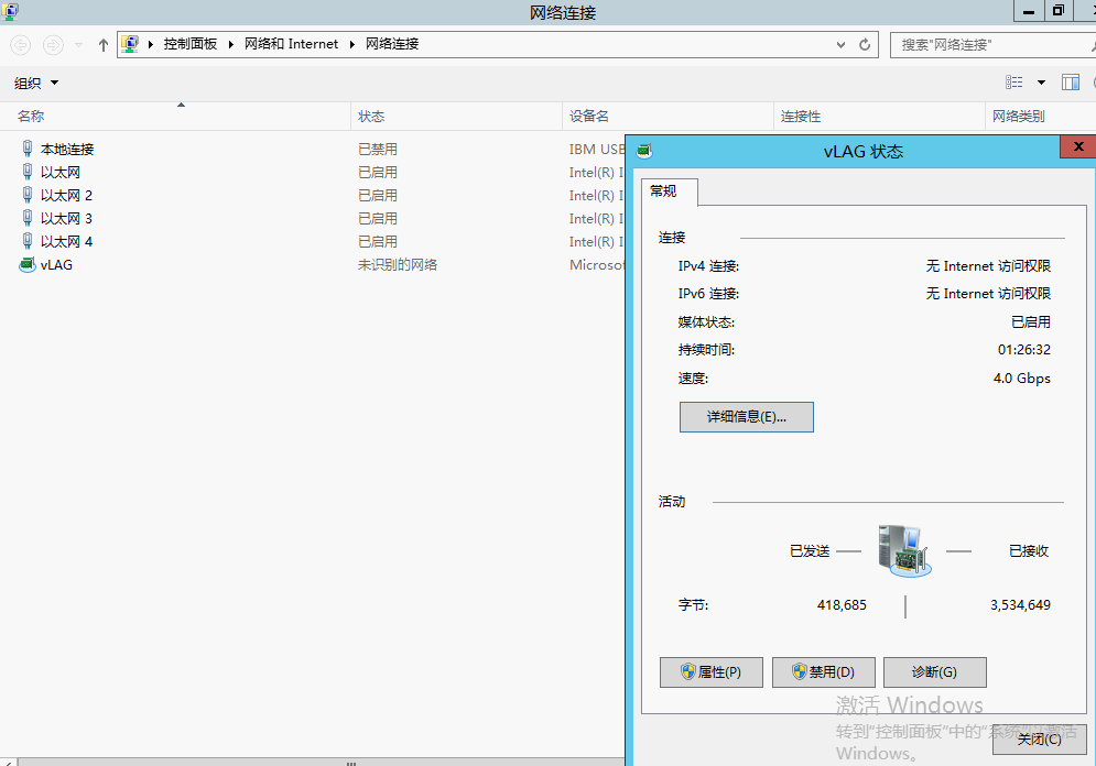
设置完成后显示,注意这里显示的带宽是4Gbps:
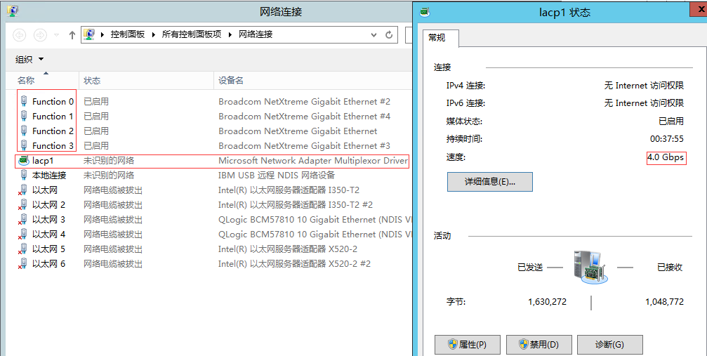
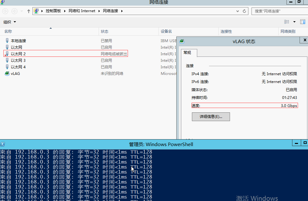
模拟其中一个端口掉线,网络通信正常,整体带宽相应减少为3Gbps。通过以上设置可以实现链路带宽、实现
链路传输弹性和冗余高可靠性。需要注意的是:无论有多少条链路聚合在一起,同一个会话只会在一条链路
传送。

vLAG配置
vLAG技术优势
现代数据中心网络日益趋向偏平化、分布式,以满足高性能服务器集群、服务器虚拟化以及云计算的需求,
VLAG是联想目前实现上述网络最成熟、最实用的技术之一。
Lenovo VLAG主要有以下具体优点:
● 克服传统网络的限制
- 克服生成树协议造成的带宽及设备的资源的牺牲(50%)
- VLAG网络中所有链路都处于激活状态,实现二层的双活
● 实现扁平、分布式网络 - 两层架构(spine and leaf)
- 实现一定规模的大二层网络
● VLAG之间的数据交换不跨VLAG Peer,实现本地交换 - VLAG Peer之间MAC地址同步
● 实现三层双活 - 与上游三层区域的设备进行配合(如OSPF BGP etc.)
- VLAG与VRRP相结合,实现active-active模式,实现双网关
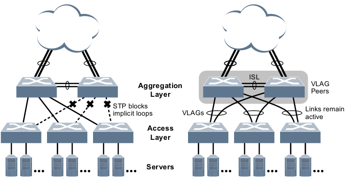
传统生成树网络 vs VLAG网络
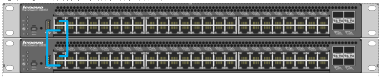
1,硬件准备
ISL是两台交换机之间的心跳线,通过ISL两台交换机进行协商同步,最终两台交换机互形成一对VLAG
Peer,外部网络可视其为一台逻辑交换机,其中一台的角色是Master,另一台为Secondary角色。ISL
线路对于VLAG至关重要,如果ISL线路我失效,那么意谓一对VLAG Peer解体,处于Secondary角色的
交换机的所有VLAG连路自动关闭(健康检测机制正常状态下),以避免网络环路LOOP的产生。为了ISL
的安全可靠,建议至少用两条物理链进行绑定(EtherChannel或LACP),在配置上即使是一条物理链路
也要进行绑定。实验中上下分别面为G8052-2,G8052-1。端口1,2进行LACP绑定, 作为ISL链路和健康检
查线。注意:需要使用Standalone FW,Stacking FW不支持vLAG。刷新微码参考前文。
2,配置步骤
a). 建立网络中所要使用的VLAN,及ISL专属的native VLAN
G8052-1(config)# vlan 4000
G8052-1(config-vlan)# interface port 1,2
G8052-1(config-if)# switchport mode trunk
G8052-1(config-if)# switchport trunk allowed vlan 1,4000
G8052-1(config-if)# switchport trunk native vlan 4000
G8052-1(config-if)# lacp key 12
G8052-1(config-if)# lacp mode active
注:(在G8052-2上进行相同的步骤,lacp mode 也可以设置成passive)
b). 建立VLAG Peer
指定VLAG tier-id(两台交换机一定要相同)
G8052-1(config)# vlag tier-id 1
指定前面准备好的LACP绑定为ISL
G8052-1(config)# vlag isl adminkey 12
c). 开启VLAG
G8052-1(config)# vlag enable
注:(在G8052-2上进行相同的步骤)
检查VLAG-Peer是否建立成功
G8052-1(config)# show vlag information
vLAG Tier ID: 1
vLAG system MAC: 08:17:f4:c3:dd:00
Local MAC a4:8c:db:52:92:00 Priority 0 Admin Role SECONDARY (Operational Role SECONDARY)
Peer MAC a4:8c:db:52:6f:00 Priority 0
Health local 0.0.0.0 peer 0.0.0.0 State DOWN
ISL trunk id 53
ISL state Up
VLAG FDB refresh state: Enable
Auto Recovery Interval: 300s (Finished)
Startup Delay Interval: 120s (Finished)
Peer Gateway State: disabled
vLAG 53: config with admin key 34, associated trunk down, state down
注:(在G8052-2上进行相同的步骤)
d). 建立健康检测(可选)
VLAG除了必须的ISL心跳线外,还强烈建议设置健康检测(health check),健康检测的作用是检查ISL是否
正常,如果发现ISL不正常,处理VLAG Secondary角色的交换机会自动把其上的所有形成的VLAG链路关闭掉,以
免产生网络环路。健康检测线要在物理在与ISL分开。
配置健康检测的对方IP地址
G8052-1(config)# vlag hlthchk peer-ip 192.168.55.50
G8052-2(config)# vlag hlthchk peer-ip 192.168.55.49
e). 检查状态
G8052-1(config)# show vlag information
vLAG Tier ID: 1
vLAG system MAC: 08:17:f4:c3:dd:00
Local MAC a4:8c:db:52:92:00 Priority 0 Admin Role SECONDARY (Operational Role SECONDARY)
Peer MAC a4:8c:db:52:6f:00 Priority 0
Health local 192.168.55.49 peer 192.168.55.50 State UP
f). 分别在两台交换机上配置普通LACP
在两台VLAG Peer G8052-1上的5,6口和G8052-2上的5,6口做端口绑定
注意:两台交换机的lacp key值一定要相同,但实际的端口号可以不同
G8052-1(config)# interface port 5,6
G8052-1(config-if)# lacp key 5,6
G8052-1(config-if)# lacp mode active
G8052-2(config)# interface port 5,6
G8052-2(config-if)# lacp key 56
G8052-2(config-if)# lacp mode passive
g). VLAG绑定
G8052-1(config)# vlag adminkey 56 enable
G8052-2(config)# vlag adminkey 56 enable
检查VLAG(Peer)绑定状态
G8052-1(config)# show vlag information
vLAG Tier ID: 1
vLAG system MAC: 08:17:f4:c3:dd:00
Local MAC a4:8c:db:52:92:00 Priority 0 Admin Role SECONDARY (Operational Role SECONDARY)
Peer MAC a4:8c:db:52:6f:00 Priority 0
Health local 192.168.55.49 peer 192.168.55.50 State UP
ISL trunk id 53
ISL state Up
VLAG FDB refresh state: Enable
Auto Recovery Interval: 300s (Finished)
Startup Delay Interval: 120s (Finished)
Peer Gateway State: disabled
vLAG 53: config with admin key 56, associated trunk down, state down
h). 检查VLAG Client的端口绑定状态
G8052-1(config-if)# show lacp information
port mode adminkey operkey selected prio aggr trunk status minlinks
1 active 12 12 yes 32768 1 53 up 1
2 active 12 12 yes 32768 1 53 up 1
3 off 3 3 no 32768 – – – 1
4 off 4 4 no 32768 – – – 1
5 active 56 56 individual 32768 – – down 1
6 active 56 56 individual 32768 – – down 1
G8052-2(config-if)# show lacp information
port mode adminkey operkey selected prio aggr trunk status minlinks
1 active 12 12 yes 32768 1 53 up 1
2 active 12 12 yes 32768 1 53 up 1
3 off 3 3 no 32768 – – – 1
4 off 4 4 no 32768 – – – 1
5 active 56 56 individual 32768 – – down 1
6 active 56 56 individual 32768 – – down 1
i). 到对应的服务器端进行设置NIC bond。以windows 2012r2为例:启用NIC,添加网卡接口,实验中使用
板载的4个万兆口,设置完成后显示,注意这里显示的带宽是4Gbps:
模拟其中一个端口掉线,网络通信正常,整体带宽相应减少,通过以上设置可以实现vLAG的偏平化、分布式
的网络架构。
参考配置:
G8052-1(config-if)# show running-config
Current configuration:
version “8.4.3”
switch-type “Lenovo RackSwitch G8052”
iscli-new
!
no system dhcp
no system default-ip
hostname “G8052-1”
system idle 0
!
interface port 1
switchport mode trunk
switchport trunk allowed vlan 1,4000
switchport trunk native vlan 4000
exit
!
interface port 2
switchport mode trunk
switchport trunk allowed vlan 1,4000
switchport trunk native vlan 4000
exit
!
interface port 3
shutdown
exit
!
interface port 4
shutdown
exit
!
vlan 4000
name “VLAN 4000”
!
spanning-tree stp 63 vlan 4000
!
logging synchronous level all
!
ldap-server mode enhanced
ldap-server security starttls
!
interface port 1
lacp mode active
lacp key 12
!
interface port 2
lacp mode active
lacp key 12
!
interface port 5
lacp mode active
lacp key 56
no lacp suspend-individual
!
interface port 6
lacp mode active
lacp key 56
no lacp suspend-individual
!
vlag tier-id 1
vlag hlthchk peer-ip 192.168.55.50
vlag isl adminkey 12
vlag adminkey 56 enable
!
interface ip 1
ip address 192.168.55.49 255.255.0.0
enable
exit
end
-—————————————————————————————
G8052-2(config-if)# show running-config
Current configuration:
!
version “8.4.3”
switch-type “Lenovo RackSwitch G8052”
iscli-new
!
!
!
!
!
no system dhcp
no system default-ip
hostname “G8052-2”
system idle 0
!
!
!
interface port 1
switchport mode trunk
switchport trunk allowed vlan 1,4000
switchport trunk native vlan 4000
exit
!
interface port 2
switchport mode trunk
switchport trunk allowed vlan 1,4000
switchport trunk native vlan 4000
exit
!
interface port 3
shutdown
exit
!
interface port 4
shutdown
exit
!
vlan 4000
name “VLAN 4000”
!
!
spanning-tree stp 63 vlan 4000
!
logging synchronous level all
!
ldap-server mode enhanced
ldap-server security starttls
!
interface port 1
lacp mode active
lacp key 12
!
interface port 2
lacp mode active
lacp key 12
!
interface port 5
lacp mode active
lacp key 56
no lacp suspend-individual
!
interface port 6
lacp mode active
lacp key 56
no lacp suspend-individual
!
!
!
vlag tier-id 1
vlag hlthchk peer-ip 192.168.55.49
vlag isl adminkey 12
vlag adminkey 56 enable
!
!
!
interface ip 1
ip address 192.168.55.50 255.255.0.0
enable
exit
!
!
end